Though it appears very insignificant, I assume it is very much important to know the basics of simulation.
with this in mind I present the simulation result of two basic logic gates
The AND gate and OR gate:
here is what you need to do:
Step1: open the modelsim simulator( I have downloaded this from Xilinx instead of the regular www.model.com)
Step2: Open New project.
Step3: Type the file name.
Step4: type the code in the text editor
module OR(a,b,out);
input a,b;
output out;
assign out= a|b;
endmodule
module testor;
reg A,B;
wire OUT;
OR O1(A,B,OUT);
initial
begin
$monitor($time," A=%b B=%b OUT=%b",A,B,OUT);
#10 A=0;B=0;
#20 A=0;B=1;
#20 A=1;B=0;
#20 A=1;B=1;
#20 A=1;B=1;
end
endmodule

This is the code for OR gate which includes the test bench.
then we have to compile the code,
after that we have to simulate the program.
this is done by selecting the two files, the main module and the test bench which are usually located under the work file.
Then we have to select the run command.
To watch the wave forms we have to select the View in the main toolbar in that we have the wave option.
after the wave window has opened we have to add the signals of interest to the wave window. This can be done by choosing to open the workplace under the view menu, and then dragging the objects of interest into the wave window.
I think this is all I have to explain.
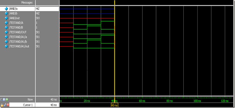
THE CODE FOR AND GATE:
module AND(a,b,out);
input a,b;
output out;
assign out = a&b;
endmodule
module TESTAND;
reg A,B;
wire OUT;
AND A1(.a(A),.b(B),.out(OUT));
initial
begin
$monitor($time,"A = %b B = %b OUT = %b",A,B,OUT);
#10 A=0; B=0;
#10 A=0; B=1;
#10 A=1; B=0;
#10 A=1; B=1;
#10 A=1; B=1;
end
endmodule
I shall give more codes later on.
Thankyou,


